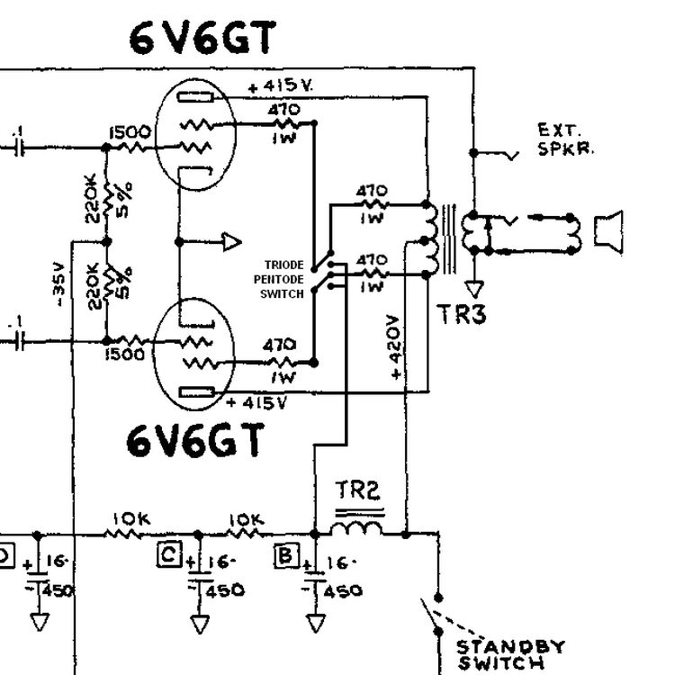
This is not a master volume and not a power-soak. It only changes how the output-tube screens are fed: normal B+ for classic pentode operation, or tied to the plates for triode operation. Same basic circuit used in the Marshall Silver Jubilee high/low power switch. Fully reversible.
What this mod does
In stock Blackface and Silverface Fenders the output tubes (6V6, 6L6, etc.) run as pentodes / beam power tubes. Screen grids (pin 4) receive B+ through the existing screen resistors (pin 6). The DPDT switch gives two modes:
| Throw | Name | Screens |
|---|---|---|
| One end | Pentode | Normal B+ through screen resistors — stock full power |
| Other end | Triode | Tied to plates (pin 3) — power drops ~40–60 % |
Preamp, reverb, tremolo, and bias network stay stock. Only the power tubes change operating mode.
Who it is for
- Blackface (roughly 1963–1967) and Silverface (1968–early 1980s) Fenders with pentode / beam-power output tubes
- 2-tube and 4-tube chassis: Deluxe Reverb, Princeton Reverb, Super Reverb, Twin Reverb, Pro Reverb, Vibrolux Reverb, Bassman, etc.
- Players who want a reversible lower-power voice without pulling tubes or adding a permanent power-soak
It is not required on amps that already have a high/low power switch.
How the stock screens are arranged
Typical AB763-family fixed-bias Fender:
B+ node (often labeled B+2 or similar) → pin6 screen resistor (470 Ω or 1 kΩ, 1–5 W) → pin 4 of each power tube.
Plates (pin 3) go to the output-transformer primary.
In pentode mode the screens sit at a fixed high voltage and the tube runs at full efficiency.
In triode mode the screens follow the plate voltage; the tube behaves more like a triode, power falls, headroom shrinks, and the harmonic content and feel change.
The primary impedance “seen” by the tubes also shifts, which is part of the different voice.
Parts
| Item | Value | Notes |
|---|---|---|
| Switch | DPDT ON–ON | Toggle or rotary; rated ≥250 V preferred. Sturdy chassis-mount (Carling-style or similar). Avoid tiny mini-toggles. |
| Wire | 20–22 AWG | High-voltage rated preferred |
| Insulation | Heat-shrink or equivalent | For every splice |
| Optional series resistors | 100 Ω or 470 Ω, 1 W | Between switch and plate in triode path only; extra screen protection, not strictly required if stock screen resistors stay in circuit |
| Stock screen resistors | 470 Ω or 1 kΩ | Leave them in place |
No extra pot. No change to the bias network. Completely reversible.
Switch placement
- Replace the ground switch as a three-prong cord must has already been installed
- Replace the rear external speaker jack — common, clean, no extra hole
Choose the location that keeps the runs short and the leads away from grid wiring. Do not drill the panel or chassis.
Exact connection points
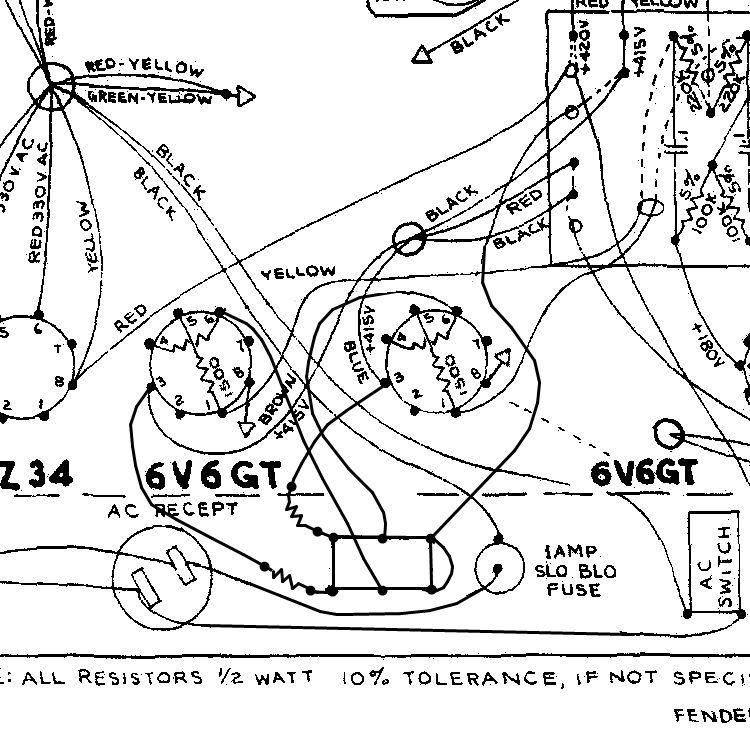
Locate the screen grid resistors on pin 4 to pin 6 of each power-tube socket. These feed from a common B+ node (or from two pair nodes that are jumpered together on 4-tube amps).
Disconnect the B+ feed that supplies the screen resistors (pin 6):
- 2-tube amp — lift the single common B+ wire feeding both screen resistors (pin 6).
- 4-tube amp — leave the left-pair screens tied together and the right-pair screens tied together; lift only the center jumper that joins the two pairs to the B+ feed.
Wire the DPDT (one pole per side of the push-pull pair):
- Common of pole 1 → screen-resistor side (pin 6) of one tube (or pair)
- One switched terminal of pole 1 → plate (pin 3) of the same tube(s)
- Common of pole 2 → screen-resistor side (pin 6) of the other tube (or pair)
- Corresponding switched terminal of pole 2 → plate (pin 3) of the other tube(s)
- The two remaining terminals (same end of the switch) → join together and reconnect to the original B+ feed you disconnected
In one throw the screens receive normal B+ (pentode). In the other throw the screens are tied to the plates (triode). The stock screen resistors stay in the circuit at all times; they continue to protect the screens.
Optional — insert a small resistor (e.g. 100 Ω or 470 Ω) between each switch-to-plate connection for extra screen protection in triode mode.
Step-by-step
- Photograph the power-tube sockets, screen resistors, and B+ feed point.
- Unplug the amp. Wait. Discharge the filter caps with a proper resistor bleed. Confirm every B+ node with a meter.
- Identify the screen resistors and the B+ wire(s) that feed them.
- Lift the B+ feed as described above (single wire on 2-tube; center jumper on 4-tube).
- Mount the DPDT switch in the chosen location.
- Wire the two poles: commons to the screen-resistor sides (pins 6), one pair of switched terminals to the plates (pins 3), the remaining pair joined and returned to the original B+ feed.
- Keep the original screen resistors in circuit. Add optional 100 Ω or 470 Ω series resistors on the plate legs for extra screen protection in triode mode.
- Insulate every splice. Dress leads away from grid wires and high-impedance points.
- Check continuity with a meter, amp off: pentode throw should show the screens connected to the B+ feed through the screen resistors; triode throw should show screens connected to their respective plates.
- Power up on a limiter. Check for red-plating or abnormal screen current.
- Listen pentode vs triode at modest volume. Confirm bias and plate dissipation after the amp is warm.
On PCB reissues the pads are often single-sided and fragile. Use a temperature-controlled iron and do not linger on a pad.
What you will hear
- Pentode — stock Blackface / Silverface: full power, classic Fender response, firm headroom.
- Triode — lower power (~40–60 % reduction typical), earlier breakup, smoother / more compressed grind, altered harmonic content and feel. Volume drops noticeably but the change is more about touch and tone than pure attenuation.
The preamp, reverb, and tremolo circuits are untouched. Both channels hear the same power-amp voice because the switch sits after the phase inverter.
Why this switch and not pulling tubes
Pulling two tubes in a 4-tube amp changes the reflected impedance by roughly half and leaves you with a mismatch on most Fender OTs that have no secondary selector. The triode/pentode switch works on both 2-tube and 4-tube chassis and does not create that mismatch. It is the same approach used in the Marshall Silver Jubilee high/low power circuit.
Bias usually needs little or no change, but always verify plate dissipation after installation. Some players live in triode; others keep the switch in pentode most of the time and flip it only when the room demands lower power.
Pros
- Works on 2-tube and 4-tube Fenders
- Fully reversible — restore the original screen-to-B+ wiring and the amp is stock
- No permanent impedance mismatch
- Useful lower-power voice without a master volume or attenuator
- Same topology as proven Marshall high/low power switches
- Screen resistors stay in circuit for protection
Cons
- Requires a high-voltage-rated DPDT and careful lead dress
- Triode power reduction is approximate (tube, OT, and voltages affect the exact number)
- Adds a switch that must be labeled so the next tech understands the two positions
Compatibility
Good candidates — Deluxe Reverb, Princeton Reverb, Super Reverb, Twin Reverb, Pro Reverb, Vibrolux Reverb, Bassman, and other Blackface / Silverface fixed-bias chassis with 6V6 or 6L6 (or equivalent) output tubes and accessible screen resistors.
Needs extra care — ’65 reissues and other single-sided PCB amps. Chassis where the rear jack space is already occupied. Amps with unusual screen supply arrangements or presence networks that interact with the power stage in unexpected ways.
Not ideal — amps that already use the rear external speaker jack or the ground-switch hole for another mod, or chassis with neither location free.
Optional follow-ons
These are not required for the switch to work.
- Use a DPDT 3-position switch (ON-OFF-ON) to expand functionality. Achieve a bonus center position that acts as a true signal mute rather than a traditional high-voltage standby mode.
- Label the two throws Pentode / Triode (or Full / Low) on the chassis lip or switch itself.
- Add 100 Ω or 470 Ω series resistors on the plate legs in the triode path for extra screen protection.
- Combine later with a master volume, power scaling, or attenuator if still more reduction is needed.
Troubleshooting
| Symptom | Likely cause |
|---|---|
| No difference between throws | B+ feed never lifted, or both poles wired to the same side |
| Triode same as pentode | Plate connections missing or shorted to the B+ side |
| Red-plating or high screen current | Screen resistors out of circuit, wrong pin, or shorted switch |
| Hum or noise after the job | Lead dress near grids, or a floating B+ splice |
| One side of the push-pull silent | Only one pole of the DPDT wired, or a bad solder joint on that side |
| Thin / weak on both throws | Wrong B+ node used, or OT primary connections disturbed |
Correct wiring gives two clear modes. Check with a meter first, amp off: pentode shows screens to B+ through the screen resistors; triode shows screens to their plates. Then power up on a limiter and verify voltages and dissipation.
Bottom line
One DPDT ON–ON switch. Lift the B+ feed to the screen resistors, send the screens to the switch commons, return one throw to B+ (pentode) and the other throw to the plates (triode). Stock screen resistors stay in circuit. Power drops roughly 40–60 % in triode with a smoother, earlier breakup. Remove the switch and restore the original screen-to-B+ wiring, and the amp is stock again.