Why You Need One
- Silent bench testing: bias calibration, signal tracing, and burn-in don't require the amp to actually make noise through a speaker.
- Protects the output transformer: the single most expensive, hardest-to-replace part of most vintage amps, and the part most at risk from an accidental no-load power-up.
- Repeatable, known load: unlike a speaker (whose impedance varies with frequency and excursion), a purely resistive dummy load presents a flat, predictable impedance, which is exactly what bias and signal-tracing work wants.
Materials
| Qty | Item | Spec | Notes |
|---|---|---|---|
| 4 | Power resistor | 4Ω, 50W, non-inductive wirewound — Aluminum Housed Metal Case Wire Wound specifically, not standard wirewound | Forms the tapped series chain per the wiring guide |
| 1 | Resistor | 10kΩ, 1W | Bleeder/reference resistor |
| 1 | Heatsink | Sized to dissipate the resistors' combined continuous wattage | The 50W resistors need real thermal mass, not just free air |
| 1 | Enclosure | Ventilated metal | Houses the whole assembly |
| 1 | Speaker jack | 1/4″ mono, tip + sleeve | Amp connection |
| 1 | BNC jack | Panel-mount | Oscilloscope output |
| 1 | Selector switch | SPDT, on-off-on, 3-position | Selects the tap point |
| — | Heavy-gauge wire | Sized to the continuous current at rated power | Throughout |
How It Works
All four resistors sit in one continuous series chain from the jack's tip terminal. The jack's sleeve is permanently wired to the far end of that chain — so the amp always sees a complete path through all four resistors (16Ω) even with the switch left untouched. The switch's job is simply to short a point further up the chain back to the sleeve line, which routes current around whatever resistors sit downstream of that point:
- Up — shorts the sleeve back to the point after R1. Only R1 carries current.
- Off (center) — nothing shorted. Current flows through all four resistors.
- Down — shorts the sleeve back to the point after R2. R1 and R2 carry current; R3 and R4 are bypassed.
Only one signal path is ever being redirected (the tap point), so a single-pole switch is all this circuit needs — the sleeve/return line is hard-wired separately and never touches the switch.
Schematic
Wiring Steps
- Wire the four resistors in one continuous series chain: R1 → R2 → R3 → R4, leaving a free lead at each end.
- Connect the jack's tip to R1's free lead.
- Connect the jack's sleeve directly to R4's free lead (the far end of the chain). This connection does not go through the switch.
- Run a wire from the node between R1 and R2 to the switch's “up” contact.
- Run a wire from the node between R2 and R3 to the switch's “down” contact.
- Wire the switch's common terminal to the same sleeve line from step 3.
- Wire the 10kΩ resistor and BNC scope tap exactly as described — this branch taps off the jack's tip line independently and isn't affected by the switch.
- Label the enclosure clearly with the wattage for each position (see table below) before final assembly.
Wattage by Position
| Switch Position | Impedance | Resistors Carrying Current | Rated Wattage |
|---|---|---|---|
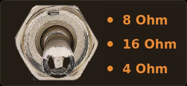
| Up (ON) | 8Ω | R1 + R2 | 100W |
| Center (OFF) | 16Ω | R1 + R2 + R3 + R4 | 200W |
| Down (ON) | 4Ω | R1 only | 50W |
Safety Feature
A 10kΩ resistor is wired in series with the BNC scope jack. If you accidentally short the scope leads together, this resistor limits the current so the box remains safe and protected.
How to Use the Dummy Load
- Connect the amp. Plug a speaker cable from your amplifier's speaker output into the input jack of the dummy load.
- Select impedance. Set the switch to match the expected load of your amplifier (4Ω, 8Ω, and 16Ω).
- Hook up your scope. Connect a standard BNC cable from the BNC jack on the box to your oscilloscope.
- Test. Inject your audio signal into the amplifier and monitor the waveform safely on your scope without generating excessive acoustic noise in your workspace.
Put it straight to work in the Initial Startup Guide or when biasing an amp on the bench.